
- #3 resistor npn transistor amplifier how to#
- #3 resistor npn transistor amplifier plus#
- #3 resistor npn transistor amplifier free#
If you have any suggestions on how to accomplish this i'd be most grateful. so it may be possible that some of the bend points i've bridged with momentary squids have the same polarity - I would just like to digitize those momentary switches so i can execute them with a python script.

#3 resistor npn transistor amplifier free#
I didnt want to say it in the top of this post but the project is to control a circuit bent video box and I'm not sure if that's frowned upon here as you guys seem to highly value accuracy, discipline and theory whereas circuit bending leans towards free spirited and ignorant abuse of gadgets (also this project may be slightly dangerous as the box in question is plugged into mains via a 9v 1.2A dc brick which i'm also assuming i'll have a good lecturing to about - I did say the bit about ignorant abuse right?). based on what you and others have said here it's clear that a transistor in general is the wrong solution.

No need to apologize, if i am misinformed about something i prefer to be corrected.

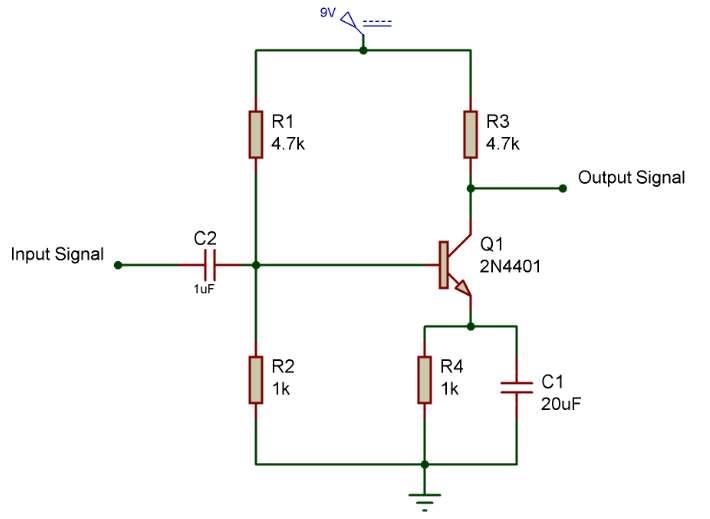
Sorry for the wall of text but it grinds me a bit when there are SO many misconceptions about simple electronic components. If it need more then we should look at a different solution. Anything between 1.5K and 3.3K should work fine if your load will draw less than about 50 mA when on. The resistor you need will be about (3.3V - 0.6V) x 100 / 100 mA = 2.7K. The output from this will not go any higher than 3.3V - 0.6V = 2.7V at best and watch that the +12V or +40V or whatever is not so high that it causes the transistor to dissipate a lot of heat or it wont last long. If you want HIGH then connect the collector to some positive supply (+3.3V to +12V), the base through the same resistor and the emitter to the load which is then connected to 0V. The collector can then be connected to the LOAD which will have to be connected from a positive power supply (+3.3V +40V) to said collector. If you want LOW output then ground the emitter and put a resistor of a certain value between the GPIO and the base. To drive one from a GPIO which goes high at 3.3V (I assume it will drive sufficient current for your purpose) then we still have to choose whether you want the final output to go HIGH or LOW when the GPIO goes HIGH. BJT transistors are not Voltage-controlled but Current-controlled devices. If we deal with an NPN BJT only (we could talk about any of the other types as a solution to your problem - but then I would have to know more about your problem), then you could use any garden variety NPN such as 2N2222 or 2N3904 which can be had at any reputable (or not-so reputable) electronics component dealer for cheap.
#3 resistor npn transistor amplifier plus#
Transistors do not "trigger", as if to say that nothing happens before a certain voltage is reached and then it "flips" or "latches" at that voltage plus 0.0000001 V.Īnd Emitter-Base junctions are never operated Reverse biased, always Forward-biased. It is the guaranteed tolerable maximum reverse-bias Voltage applied to the Emitter- Base junction with the collector Open (unconnected) before the device may be damaged. The Vebo is not the voltage that it "triggers" at. You are not reading the datasheet correctly. I take it you are looking for a BJT (Bipolar Junction Transistor) which is one of two large classes of transistors (the other is FET transistors) and which come in two general types: PNP and NPN.


 0 kommentar(er)
